Introduction
The Disconnect Operation is an operation used to delete the association between instances of two entities (the source entity and the target entity), connected by a predefined relationship role.
The Disconnect Operation can manage single instances or sets of instances to disconnect:
- One instance of the source entity from a set of instances of the target entity (and vice versa). For example, suppose you have the "Company" and the "Employee" entities connected with the 1 to N relationship role. You can use this operation to remove the associate of the employees with a company.
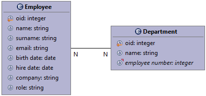
- Sets of instances of target and source entities with the same cardinality (performing a pairwise disconnection). For example, suppose you have the "Employee" and the "Departments" entities connected with the N to N relationship role. You can use this operation to remove the association from a set of employees to a set of departments.
NOTE. The operation is usually used for manage the many to many relationship modeled in the Domain Model.
Source and target entity disconnections are chosen applying conditional expressions.
Properties
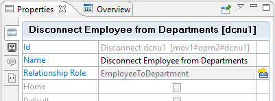
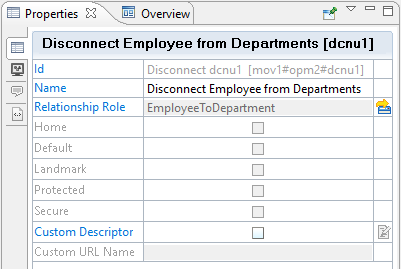
- Id. The unique key automatically assigned by WebRatio Platform to identify the operation (e.g., "dcnu1").
- Name. A meaningful name for the operation, used as label (e.g., "Disconnect Employee from Departments").
- Relationship Role. The Domain Model Relationship Role on which the operation is based (e.g., "EmployeeToDepartment").
Configuration
A disconnect operation can be configured through a context menu that can be reached with a right-click on the operation either in the work area or in the Outline View. The context menu contains the following options:
- Add > Flow. Adds an outgoing data flow to the operation, which can be used to transport information to other elements.
- Add > OK Flow. Adds an outgoing OK flow to the operation. The OK flow is activated when the operation performs correctly, it can be used to transport information, and it will cause the execution of its target element.
- Add > KO Flow. Adds an outgoing KO flow to the operation. The KO flow is activated when the operation is not able to perform correctly, it can be used to transport information, and it will cause the execution of its target element.
- Add > Property. Adds a custom property to the operation. A property is composed of name and value and permits to mark the element for different purposes.
- Add > Source Key Condition. Adds a key condition to the source entity of the selected relationship role. This condition restricts the set of the available source entity instances through the primary key.
- Add > Source Attributes Conditions. Adds an attributes condition to the source entity of the selected relationship role. This condition restricts the set of the available source entity instances.
- Add > Source Relationship Condition. Adds a relationship role condition to the source entity of the selected relationship role. This condition restricts the set of the available source entity instances.
- Add > Target Key Condition. Adds a key condition to the target entity of the selected relationship role. This condition restricts the set of the available target entity instances.
- Add > Target Attributes Condition. Adds an attributes condition to the target entity of the selected relationship role. This condition restricts the set of the available target entity instances.
- Add > Target Relationship Role Condition. Adds a relationship role condition to the target entity of the selected relationship role. This condition restricts the set of the available target entity instances.
Input and Output
The Input and the Output of the operation are accessible through the Parameters Binding dialog of incoming and outgoing flows, respectively.
Input
You can access to the input parameters by opening the Parameters Binding dialog by double-clicking or by selecting the Binding property on an incoming flow to the disconnect operation. Here you can find the conditions of the target and source entities of the selected relationship role named with suffix [Target] and [Source].
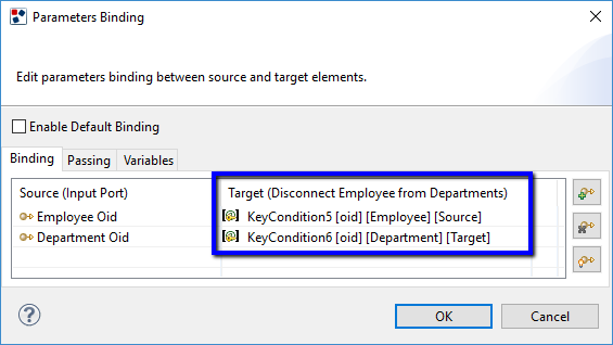
The input of the disconnect operation consists of all the conditions defined on the target and source entities of the relationship role on which the operation is defined.
In this example, the available conditions are related to the N to N relationship role modeled between the "Employee" and the "Department" entities.
Output
You can access to the output parameters by opening the Parameters Binding dialog by double-clicking or by selecting the Binding property of an outgoing flow from the disconnect operation.
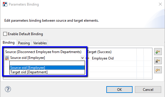
Here all the Output Parameters can be bound with the Input Parameters of the target element.
The output of the disconnect operation consists of the key attributes of the entities connected by the relationship role on which the disconnect operation is defined. The entity to which the key attributes refers is specified in brackets.
In this example, the available key attributes refer to the "Employee" and the "Department" entities.
Example
The purpose of this section is to show the usage of the disconnect operation through examples. Suppose you have two entities in the Domain Model: "Employee" and "Department", and they are connected with an N to N relationship role.
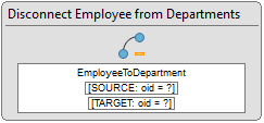
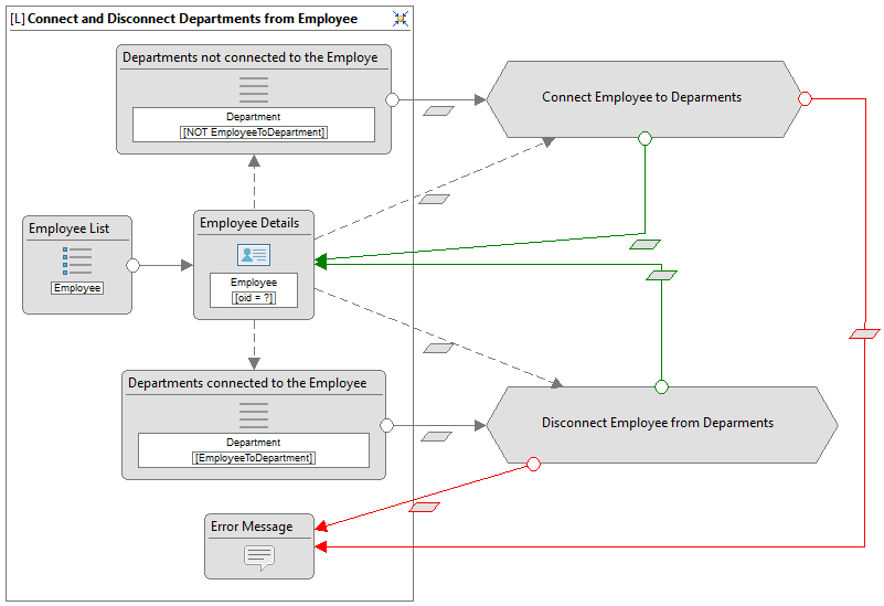
Suppose you want to give the user the chance to select an employee and disconnect some departments connected to him/her. The resulting IFML model is shown in the following figure.
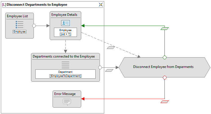
The "Disconnect Employee from Departments" action definition is modeled in this way:
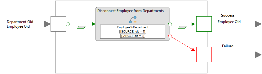
Model the action definition as shown in the previous image and let's take a detailed look at the steps necessary for configuring the "Disconnect Employee from Departments" disconnect operation:
- Select the Disconnect Operation.
- Move to its Properties View to define the Data Binding connection.
- Change the Name property (e.g., "Disconnect Employee from Departments").
- Set the relationship role on which the disconnect operation is based, pressing on the Select button next to the Relationship Role property, choose the "EmployeeToDepartments" relationship role from the opened dialog and then press the OK button.
- Define the input parameters. Double-click on the input OK flow to open the "Parameters Binding" dialog. Uncheck the Enable Default Binding property and bind the key attributes to the related key conditions. Then press the OK button.

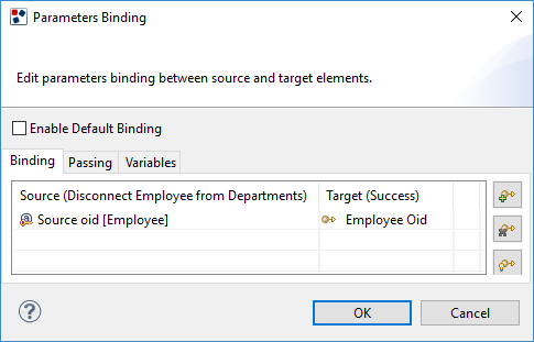
- Define the output parameters. Double-click on the output OK flow to open the "Parameters Binding" dialog. Uncheck the Enable Default Binding property and bind the "Source oid [Employee]" parameter. Then press the OK button.
Now that the definition is complete, let's open the "Home" site view and complete the IFML model.
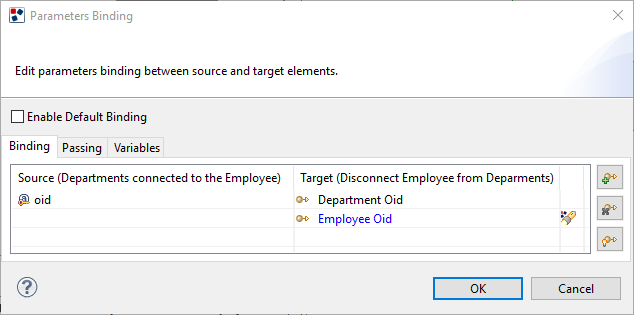
- Define the Parameters Binding of the "Disconnect" navigation flow. Double-click on the navigation flow to open the "Parameters Binding" dialog. Uncheck the Enable Default Binding property and bind the "oid" attribute of the simple list with the "Department Oid" input parameter of the action. Then press the OK button.
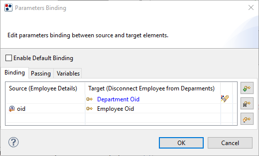
- Define the Parameters Binding of the outgoing data flow of the "Employee Details" component. Double-click on the data flow to open the "Parameters Binding" dialog. Uncheck the Enable Default Binding property and bind the "oid" attribute of the details component with the "Employee Oid" input parameter of the action. Then press the OK button.
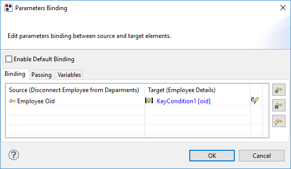
- Define the Parameters Binding of the outgoing OK flow. Double-click on the OK flow to open the "Parameters Binding" dialog. Uncheck the Enable Default Binding property and bind the "Employee Oid" output port parameter of the action with the key condition of the details component. Then press the OK button.
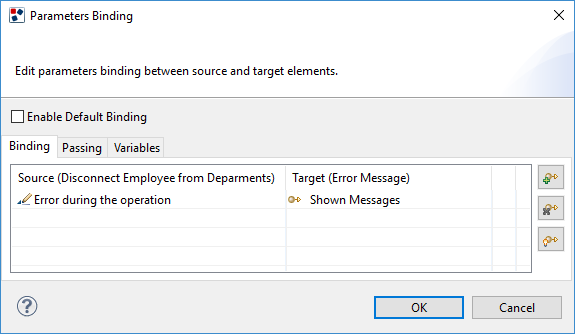
- Define the Parameters Binding of the outgoing KO flow of the action. Double-click on the KO flow to open the "Parameters Binding" dialog. Uncheck the Enable Default Binding property and write an error message string, for example "Error during the operation". Then press the OK button.
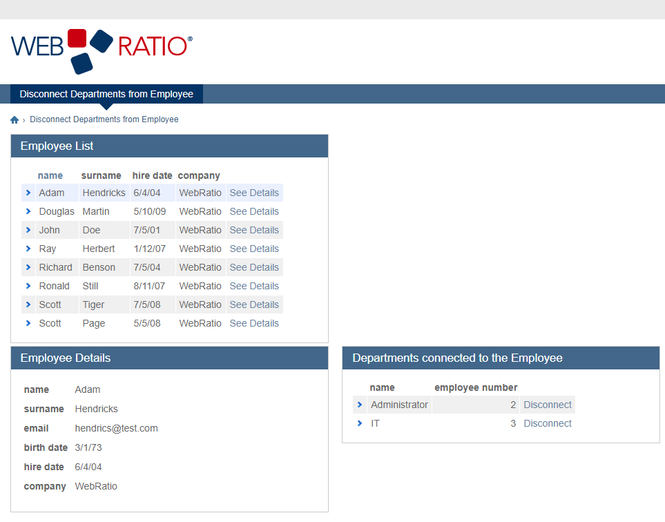
Now you can generate the Web application to see the result and it will be as shown in the following image:
Additionally, you can add to this management the Connect Operation, which allows the user to connect the employee to the departments, obtaining the following model:
Refer to the "How to use the Connect Operation" article to learn how you can integrate your model with this operation.
How to use the sample project
You can use the "DisconnectSample.zip" file attached to this article, to test the usage of the Disconnect Operation.
Follow these steps to use the project:
-
Import the sample project into the WebRatio Platform. You can learn how to do this by watching the "Organize the Workspace" online lesson.
-
Generate the project with the "Generate and Run on Cloud" command if you have a WebRatio Community Platform version; otherwise, use the "Generate and Run" command.
-
Visit http://localhost:8080/DisconnectSample/page2.do or http://freeXXXXX-freeapp.eu.webratio.net/page2.do with any browser, click on the "Disconnect Departments from Employee" menu to test the example.